Vehicle aerodynamics · Composite structures
Front Wing Design & Construction
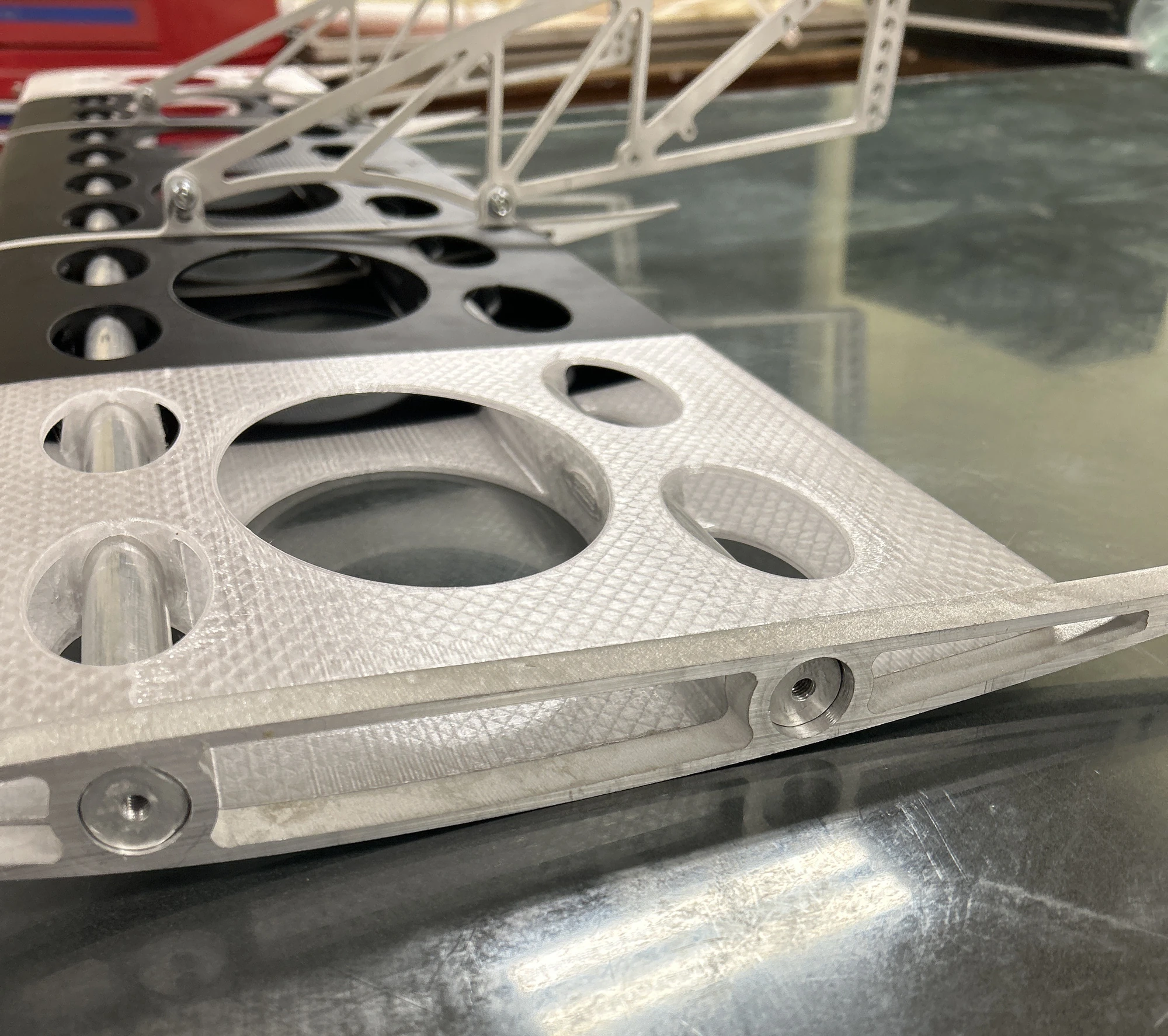
A continuous main element and hollow carbon shells developed under my leadership to improve rigidity, durability, and mass.
Overview
The 2026 Formula SAE front wing needed less mass and a stiffer, continuous main element while retaining cone-impact durability. I led the structural concept, tooling, composite manufacturing, and team training; Mathew Saffle performed the aerodynamic analysis and element placement, with mounting development shared with Kinsly Burelson. Hollow carbon shells around an aluminum main-element skeleton replaced the heavier foam-core approach. Teammate measurements indicated an approximately 10% front-wing mass reduction, and informal cone-contact and standing checks showed no obvious damage. Exact mass records and controlled structural tests remain unavailable; further aerodynamic development continues.
My Contribution
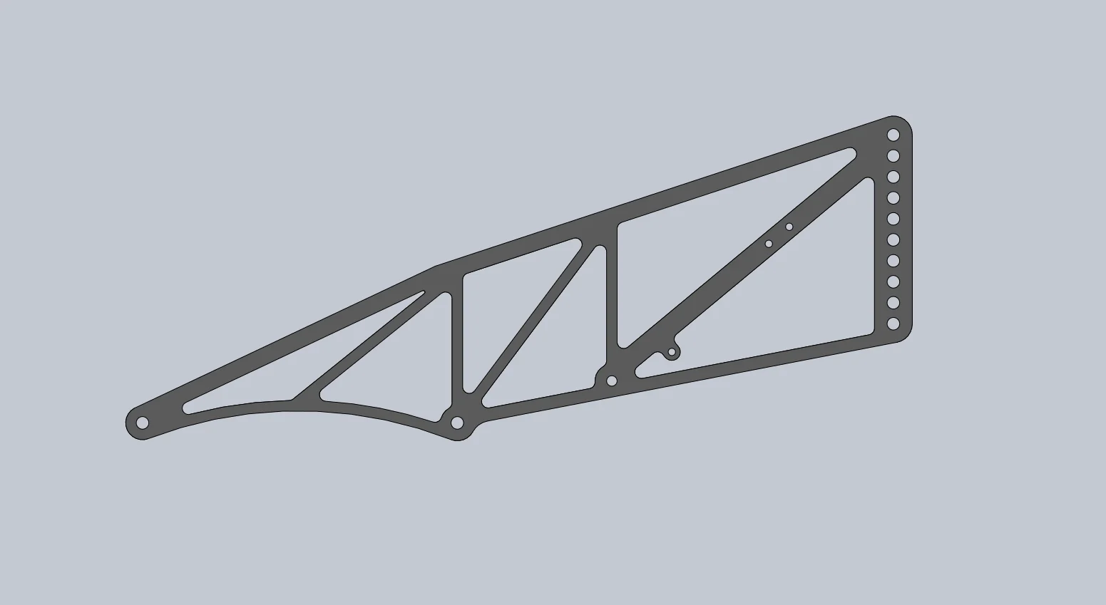
I proposed the continuous main element, hollow carbon shells, aluminum skeleton, and mechanically retained end ribs, and led the tooling and manufacturing process. I trained teammates and worked directly across fabrication while delegating tasks to build their capability. Mathew Saffle performed the aerodynamic simulations and element placement; Mathew and Kinsly Burelson developed the skeleton details. Mathew initiated the mounts and Kinsly finalized them.
Engineering Approach
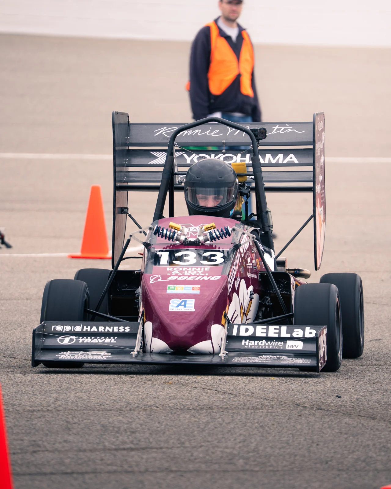
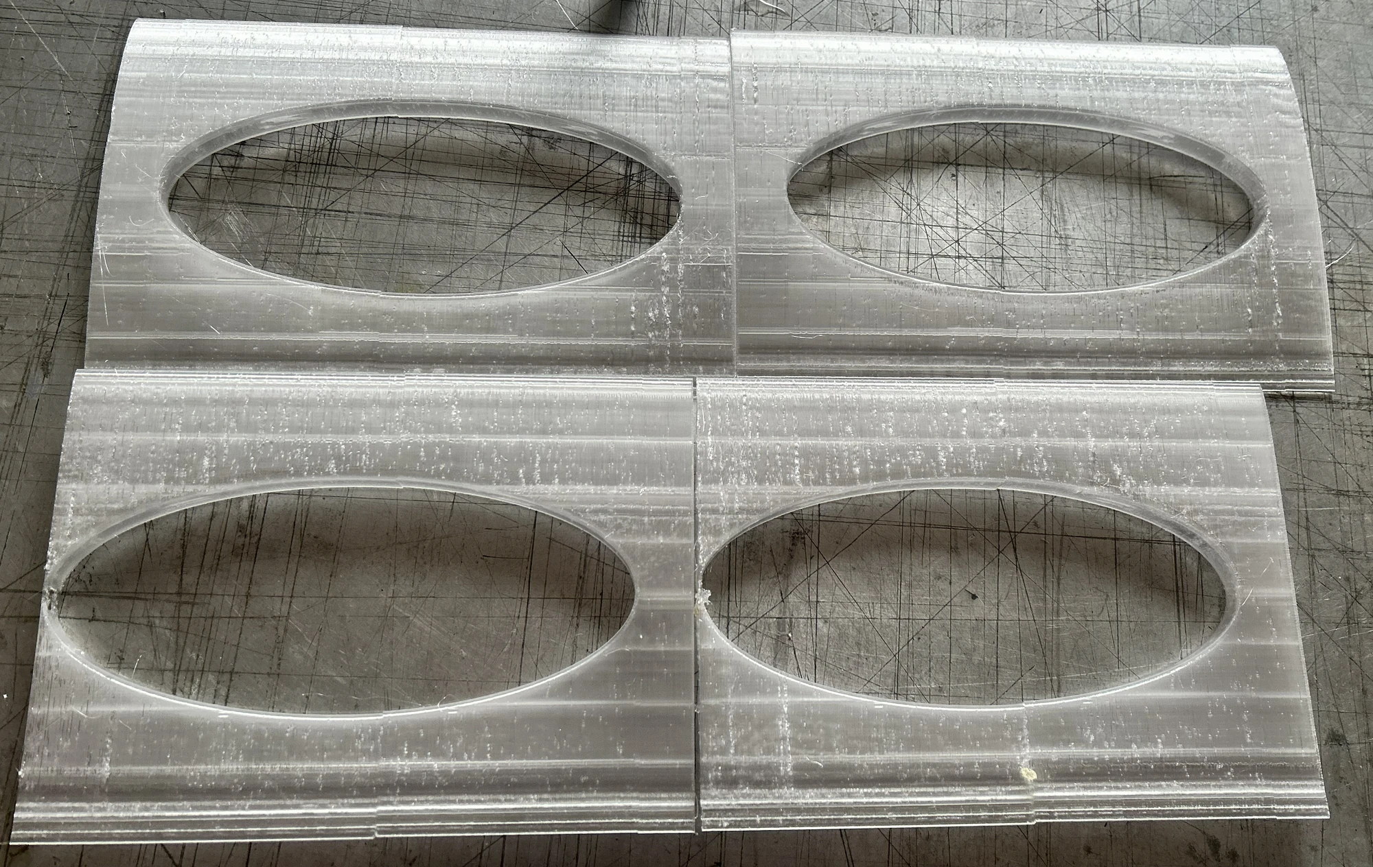
The five-element front wing consists of one full-span main element and two downstream elements on each side of the nose. Only the main element contains the aluminum skeleton; printed inserts help distribute local loads, and the smaller elements use printed reinforcement. Bolts, close-fitting ribs, and rivets retain the main-element ends. Committing to molded hollow shells required building a manufacturing capability the section had not previously used.
Results & Current Status
The driver estimated a 0.3–0.4-second practice skidpad improvement with the complete aeropackage; timing records were not retained. This does not isolate the front wing’s contribution. Based on a teammate’s measurements, the 2026 front wing was approximately 10% lighter than the 2025 front wing; exact masses and the components included in the weighing are currently unavailable. The wing survived repeated cone-contact trials, and an informal 220 lb standing check showed no obvious damage. A controlled structural test record is unavailable.
Team Credits
Section leadership, initial structural concept, tooling and manufacturing lead: David Stout. Aerodynamic analysis and element placement: Mathew Saffle. Skeleton development: Mathew Saffle and Kinsly Burelson. Mounts: initial design by Mathew Saffle, finalized by Kinsly Burelson. Fabrication: the aerodynamics section.
Next Steps
Project Images
Supporting Files & Model
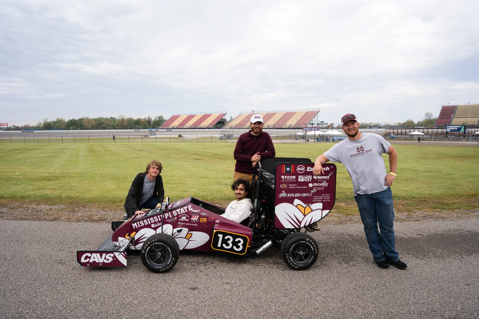
The supplied CAD export exposes the internal structure and selected shells. The vehicle photographs show the complete manufactured wing.
- 3D visualization (download GLB)
- Front-wing CAD assembly (download STEP)
- Front-wing drawing set (15 sheets) (download PDF)
- Whole-car aeropackage specification sheet (download XLSX)
The STEP download provides CAD geometry for inspection, measurement, and section views. It does not include the original SolidWorks feature history or mates.