CAM · Moldmaking · Composites
Composite Wing Tooling & Manufacturing
SolidWorks mold design, Fusion CAM, CNC machining, and repeatable carbon-shell manufacturing for the 2026 wings.
Overview
I led the design, Fusion CAM, CNC machining, and composite process for reusable MDF tooling for the 2026 Formula SAE wings. Sharing airfoil sections and chord lengths allowed seven hollow-shell airfoils, plus backups, to be produced from three female molds, trading aerodynamic flexibility for manageable tooling time. Improved CAM, cleaning methods, and trained operator coverage reduced machining time from roughly 12 to 8 hours for mirrored diffuser-mold sections. The airfoil tools produced smooth shell surfaces; the proposed diffuser was never validated or installed on the car. Seam placement and process documentation remain opportunities for improvement.
My Contribution
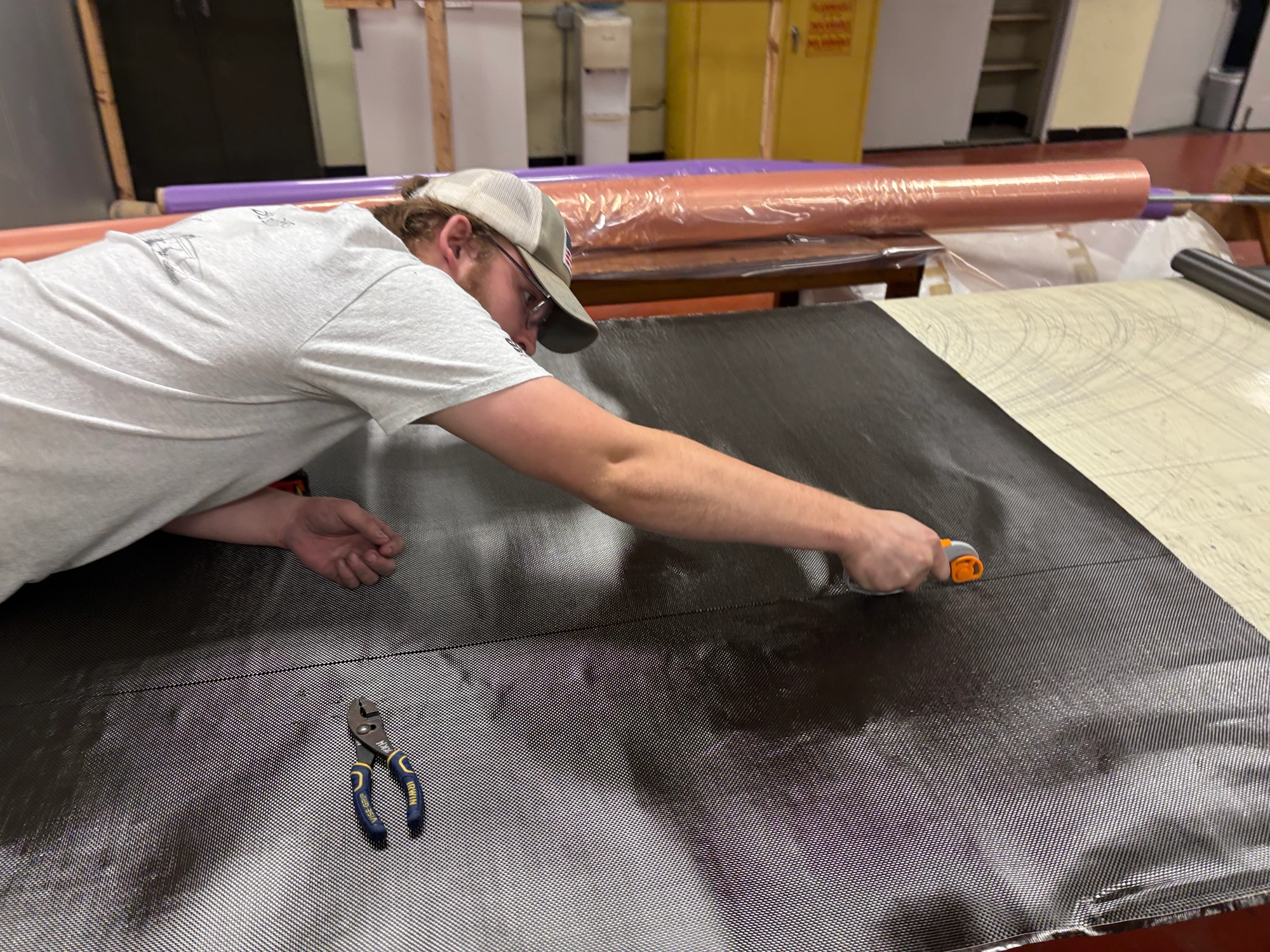
I designed the molds in SolidWorks, prepared and modeled laminated MDF stock, developed Fusion CAM, obtained faculty program review, set up and ran the Haas mills, and trained section members. Brandon Warner mentored my CAM and CNC development. I also led surface preparation and carbon manufacturing, with the section sharing layup work.
Engineering Approach
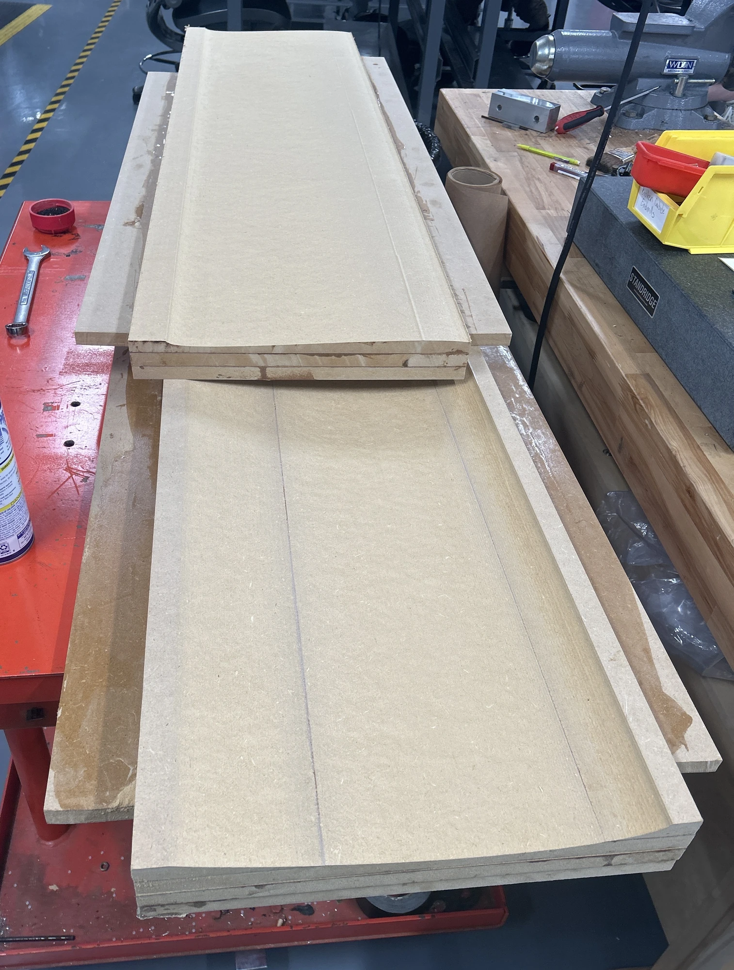
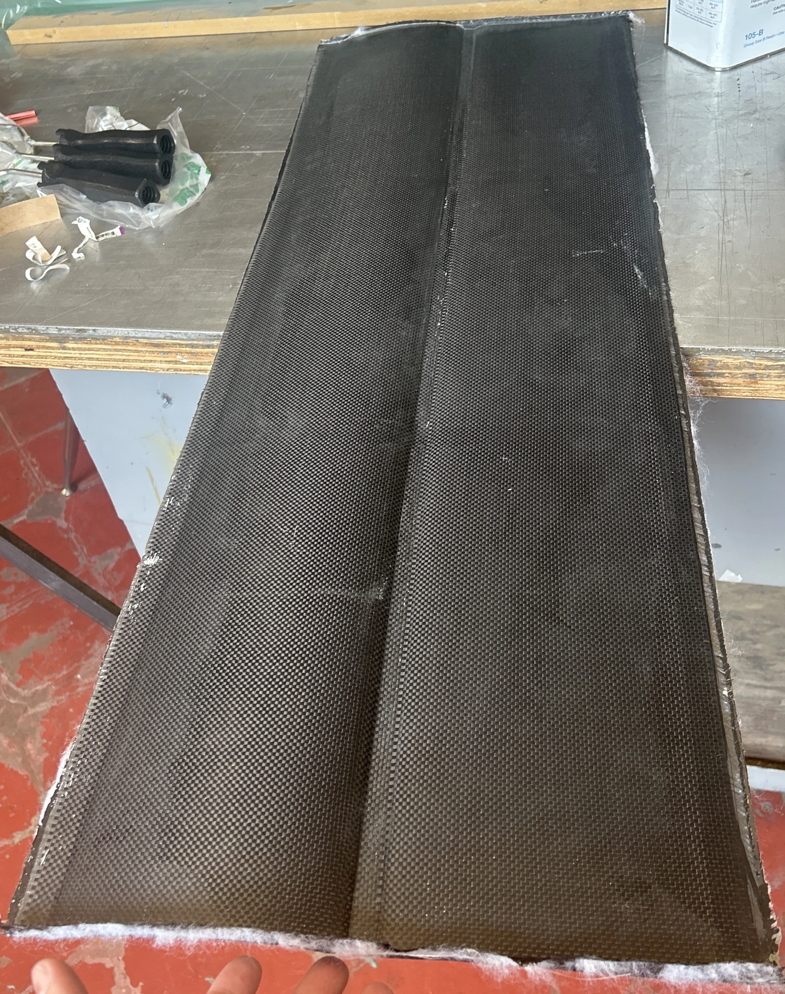
Epoxy replaced wood glue between MDF layers after weak bonding was found. The main-element top and bottom used separate female tools; secondary top/bottom cavities shared a tool that was machined in three sections on the VF1 and joined with dowels. Layups used three bidirectional-carbon layers plus an outer twill layer placed first against the female surface. During shell layup, the team pulled as close to full vacuum as practical while the molds supported the laminate. After cure, top and bottom shells were bonded around the internal structure under lower vacuum, using only enough to hold the assembly during adhesive cure without pulling the shells concave. The numerical gauge reading and units remain unconfirmed. The two tertiary elements were wrapped around printed forms rather than molded. CAM refinements, finishing tolerance, hand sanding, machine protection, and frequent dust removal balanced time and surface quality.
Results & Current Status
The reusable airfoil tools produced shell pieces for seven airfoils, plus backups, with smooth finished surfaces. Approximately ten layup runs were completed. For two mirrored diffuser-mold sections, improved CAM, cleaning methods, and trained operator coverage reduced machining time from roughly 12 to 8 hours. This comparison applies to diffuser tooling. The proposed undertray system—including the diffuser, barge boards, and wheel-wake mitigation devices—was never validated or installed on the competition car.
Team Credits
Mold design, stock preparation, CAM, CNC setup/run, and manufacturing lead: David Stout. CAM/CNC mentorship: Brandon Warner. Program review and operator approval: laboratory faculty/operations engineers. Layups and fabrication support: the aerodynamics section.
Next Steps
Airfoil Molds & Shell Manufacturing
From machined MDF tools to a finished carbon shell: selected views of the tooling, hands-on preparation, and manufacturing result.
Watch the Process
Short, silent clips. Choose Play to load a video.
Actual machining of the main-element MDF tooling, viewed across the workpiece.
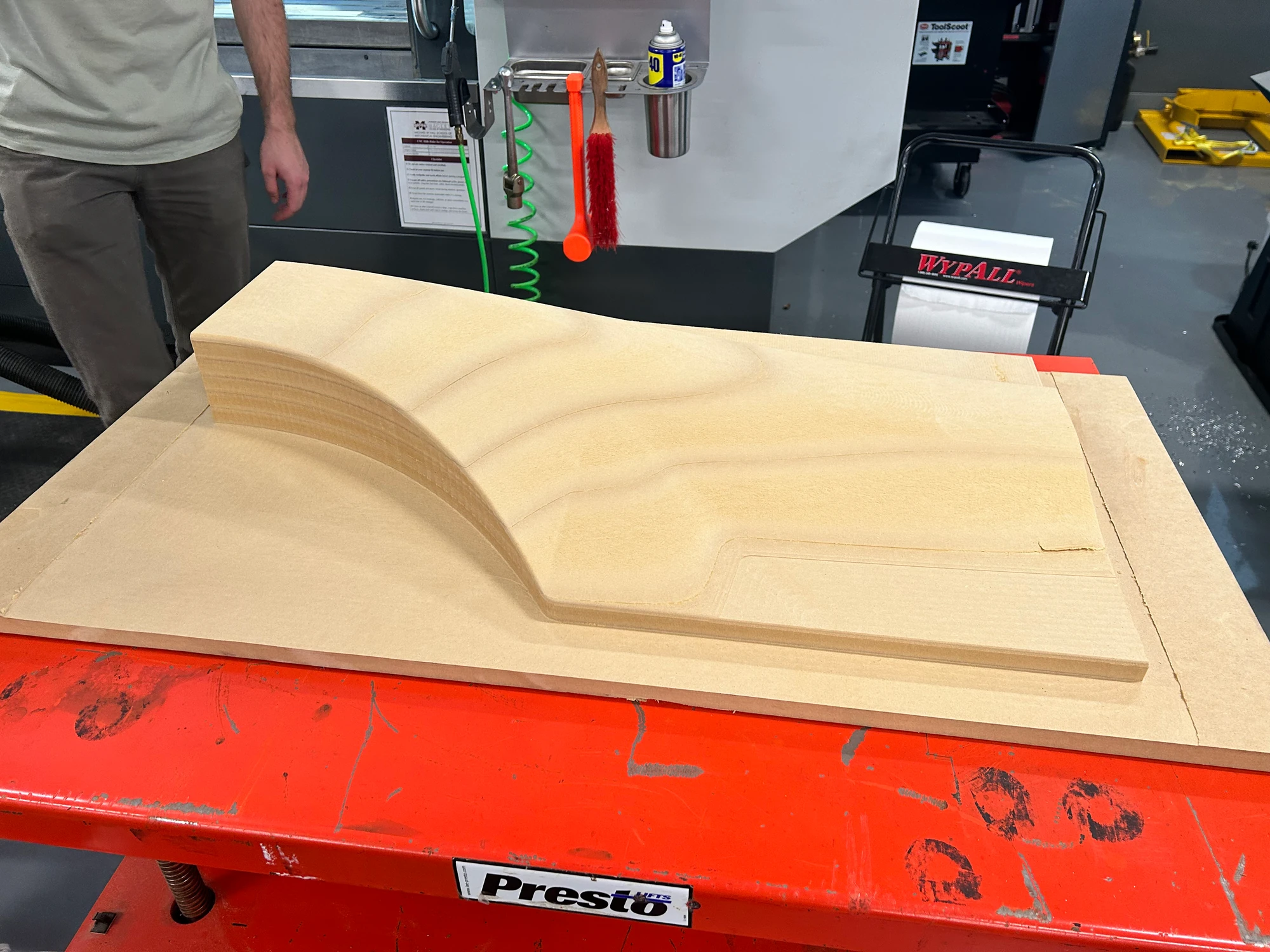
Diffuser CAM & Machining
The diffuser work demonstrates CAM development and mold machining. The proposed undertray system was never validated or installed on the competition car; these are tooling records, not evidence of vehicle aerodynamic performance.
Watch the Process
Short, silent clips. Choose Play to load a video.
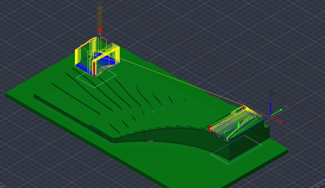
A Fusion machining simulation of the rear-section tooling. This is CAM playback, distinct from the actual machining recordings above.
Supporting Files & Models
Choose a mold to explore in 3D, then download an individual STEP or the complete bundle.
Inspect all five molds in the viewer, including the three separate secondary-mold sections. These are surface visualizations derived from the STEP exports, with an illustrative MDF color. Download a GLB from the viewer, or use the STEP files below for precise CAD inspection.
Airfoil tooling
Main-element top mold (download STEP)Airfoil tooling
Main-element bottom mold (download STEP)Airfoil tooling
Three-piece secondary mold (download STEP)Diffuser tooling
Diffuser front-section mold (download STEP)Diffuser tooling
Diffuser rear-section mold (download STEP)Complete STEP bundle
All five molds & process notes (download ZIP)
STEP geometry for inspection, measurements, and section views. The secondary mold contains three separate sections; the bundle includes all five tools and process notes. CAD feature history and executable CAM are not included.